Most electrical networks are very complex. To analyze them, the need of circuit theorems, techniques and laws are really important. Superposition Theorem, Thevenin Theorem, Norton Theorem, Maximum Power Transfer Theorem, Substitution Theorem, Millman Theorem and Reciprocity Theorem are the fundamental laws used for network analysis. All these circuit theorems helps to find the basic electrical parameters in a simpler way. The top 7 circuit theorems for network analysis are discussed below:
Superposition Theorem states that “In any linear circuit containing multiple independent sources, the current or voltage at any point in the network may be calculated as algebraic sum of the individual contributions of each source acting alone.”
To solve an electrical network or to perform network analysis using Superposition Theorem, below steps must be followed:
Example: Find current through a 6R using Superposition theorem.


This circuit theorem states that “The current flowing through a load resistance connected across any two terminals a and b of a linear and active bilateral network is given by Voc|| (Rt +RL) where VOC is the open circuit voltage and Rt is the internal resistance of the network as viewed back into the open circuited network from terminals a and b with all voltage sources replaced by their internal resistance and current sources by infinite resistance.”
Simple Steps to analyze an electric circuit using Thevein’s theorem:

Example: Find current through a 2R using Thevenin theorem in the above electrical circuit.


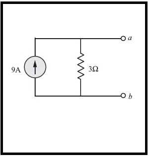
Norton’s Theorem for network analysis states that “Any linear circuit containing several energy sources and resistances can be replaced by a single constant current source in parallel with a single resistor“.
Simple Steps to analyze an electric circuit using Norton Theorem.

Example: Find the Norton Equivalent Circuit for the electrical circuit given above.


Moritz von Jacobi states the maximum power transfer theorem as, the load resistance must be equal to the source resistance when seen from the output terminals. This circuit theorem was published in the year 1840 for network analysis and is also known as Jacobi's law.

Proof: Consider the linear circuit given below. Here RL is the load resistance, Rt is the Thevenin Resistance and i is the current flowing through it.
Power delivered to the load is given by,

Here Vt is the voltage source. Now by, differentiating p w.r.t RL and equating to zero, we get, RL=Rt.

Now the maximum power given to the load resistor is found out by substituting Rt=RL.

Reciprocity Theorem states that in a linear and a single source circuit, the ratio of excitation to response is constant when the positions of excitation and response are interchanged. Now consider the circuit given below:

Applying Kirchoff's Voltage Law to mesh1, mesh2 and mesh3 we get,
KVL for mesh1: 6.375 I1-2I2-3I3 =0
KVL for mesh2: -2 I1+14 I2-10 I3=0
KVL for mesh3:-3 I1-10 I2+14 I3=-10
By solving the above equations we get, the current I1=-2A.
Now we can verify the reciprocity theorem by following the below process.
Verifying Reciprocity Theorem
Consider the redrawn circuit and the mesh equations are given below. Applying the Kirchoff's Voltage Law to mesh1, mesh2, mesh3.

KVL for mesh1: 6.375 I1-2I2+3I3 =10
KVL for mesh2: -2 I1+14 I2+10 I3=0
KVL for mesh3: 3 I1+10 I2+14 I3=0
By solving the above equations we get, I’3=-2A.
Since I1= I’3=-2A.
Hence, the reciprocity theorem is verified.
Millman's theorem is basically used to compute the voltage at the ends of a circuit made up of only branches in parallel.
Consider the circuit shown in the figure below:

Let im the current generators and Vk be the voltage generators.
Let Rk be the resistance on the branch with voltage generators.
Let Ri be the resistance on the branch with no generator.
Let Rm be the resistances on the branches with current generators. Then,


Copyright © 2024 Mepits - Designed By Digiora

